In high-power electronic assemblies, junction temperature (Tj) is the primary determinant of mean time between failures (MTBF). Standard FR-4, with an isotropic thermal conductivity of approximately 0.25 to 0.3 W/m·K, creates severe thermal bottlenecks. Aluminum Core PCBs—also referred to as Metal Core PCBs (MCPCB) or Insulated Metal Substrates (IMS)—solve this constraint through engineered thermal conduction paths.
Thermal Conduction Physics
Thermal resistance follows the relationship Rth = d / (k · A), where d is dielectric thickness, k is thermal conductivity, and A is heat spreading area. By optimizing ceramic fillers within the prepreg, thermal resistance drops by up to 88% compared to standard FR-4.
Conductivity: 1.0 – 8.0 W/m·K
Tg rating: 130°C to 180°C
Dielectric thickness: 75 µm – 150 µm
Substrate Alloy Options
The metal backing functions both as mechanical carrier and primary heat spreader. Alloy 5052 offers superior tensile strength and bending rigidity for automotive housings, while Alloy 6061 provides enhanced machinability for complex milled cavities.
Alloy 5052: High corrosion resistance
Alloy 6061: Precision CNC machining
Alloy 1060: 99.6% pure aluminum
Dielectric Breakdown Safety
Electrical safety requires isolation up to multiple kilovolts under demanding operating conditions. Our proprietary ceramic-polymer formulations deliver robust breakdown parameters, satisfying UL 796, UL 94V-0 flammability, and IEC isolation requirements.
Dielectric breakdown: 3 kV – 6 kV AC
Comparative Tracking Index (CTI): PLC 0
Insulation resistance: >106 MΩ
DFM & Fabrication Precision
Differential thermal expansion (CTE mismatch) between copper (17 ppm/K) and aluminum (23 ppm/K) demands controlled lamination pressures and specialized tooling to avoid board warpage during high-temperature reflow.
Board warp & twist: ≤ 0.5%
V-scoring residual tolerance: ±0.05 mm
Copper weight: 1 oz to 6 oz
Product Catalog & Assemblies
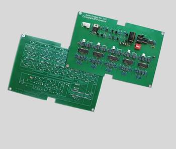
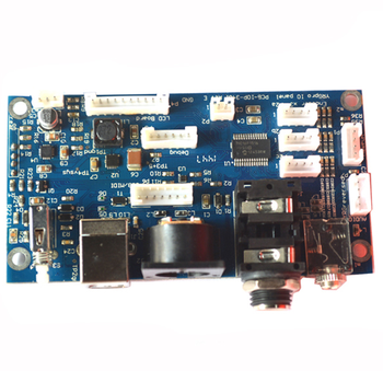
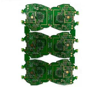
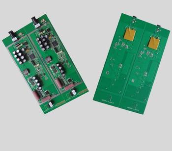
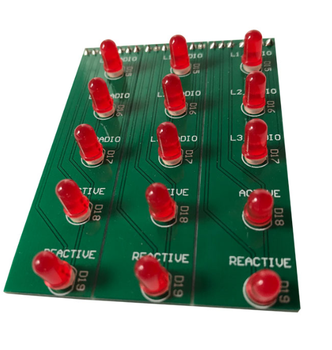
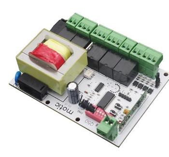
Featured Aluminum Core PCB & Power PCBA Solutions
Engineered to drawing, fully verified in Shenzhen, China. From rapid bare board fabrication to turnkey SMT assembly with component sourcing.
As AI processors, wide bandgap (GaN/SiC) semiconductors, and electric vehicle architectures advance, global sourcing teams face evolving technical and supply chain dynamics.
Shift toward Direct Thermal Path (DTP) & COB
Traditional dielectrics, even at 3.0 W/m·K, create thermal limits for extreme power densities exceeding 50 W/cm². Global buyers are actively shifting toward Direct Thermal Path (DTP) aluminum substrates, where the copper thermal pad makes direct, zero-dielectric contact with the aluminum base (or copper pedestal), achieving effective conductivity above 200 W/m·K.
Consolidation into Turnkey PCBA Partners
Procuring bare aluminum boards separately from SMT assembly introduces elevated defect risks. Because aluminum conducts heat away rapidly during reflow, assembly requires specialized thermal profile tuning and voiding management. Procurement teams are reducing risk by sourcing turnkey bare board fabrication, component sourcing, and SMT assembly under one accountable roof.
High-Voltage Automotive & CTI Requirements
With 800V EV architectures becoming industry standard, procurement specifications now mandate strict dielectric withstand voltages (over 4 kV to 6 kV) and Comparative Tracking Index (CTI) ratings of PLC 0 (600V+). Suppliers must provide batch-traceable Hi-Pot testing and partial discharge certifications.
Miniaturization via Hybrid Rigid-Flex Metal Substrates
Space-constrained aerospace, medical, and sensor assemblies are moving away from bulky external cast heat sinks. Engineers specify hybrid constructions where flex-rigid circuits fold around aluminum chassis parts, eliminating mechanical fasteners and thermal paste application labor.
Sustainability & Closed-Loop Aluminum Recycling
Western OEM procurement policies increasingly evaluate the carbon footprint of raw metal extraction. Modern fabricators in Shenzhen utilize certified low-carbon recycled aluminum alloys (5052/6061) compliant with RoHS 3, REACH, and emerging EU carbon border regulations.
Demand for Transparent Component Supply Chains
Given recent semiconductor volatilities, sourcing teams demand verifiable component traceability for power MOSFETs, GaN gate drivers, and high-lumen LEDs mounted on aluminum cores. Direct Shenzhen-hub sourcing ensures authentic parts with full manufacturer batch documentation.
Material Selection Guide
Engineering Comparison: FR-4 vs. MCPCB Variants
Select the optimal substrate and dielectric architecture based on thermal dissipation, isolation voltage, and total manufacturing cost.
Substrate Technology
Thermal Conductivity (W/m·K)
Typical Dielectric Thickness
Electrical Breakdown
Primary Target Applications
Standard FR-4 Fiberglass
0.25 – 0.3 W/m·K
N/A (Bulk substrate)
~20 kV/mm
Low-power logic, microcontrollers, general sensors
Standard Aluminum Core PCB (1.0–2.0 W)
1.0 – 2.0 W/m·K
75 µm – 100 µm
3 kV – 4 kV AC
Standard LED backlighting, consumer power supplies
High-Thermal Aluminum PCB (3.0–8.0 W)
3.0 – 8.0 W/m·K
50 µm – 75 µm
4 kV – 6 kV AC
Automotive LED headlights, stadium lights, industrial drives
Direct Thermal Path (DTP Copper/Al)
200 – 400 W/m·K (direct)
Zero under thermal pad
Requires isolated pad
Ultra-dense laser diodes, GaN power stages, EV modules
Copper Core PCB (MCCPCB)
385 – 400 W/m·K (base)
75 µm – 100 µm
3 kV – 5 kV AC
Extreme current distribution, radar transmitters, avionics
Manufacturing Authority
Why Global Buyers Partner with Shenzhen Mivo Electronics Co., Ltd.
Shenzhen Mivo Electronics Co., Ltd. is an onsite-verified electronics manufacturer operating in Shenzhen, Guangdong—the epicentre of the world's electronics supply chain. With 8 years of export operations, a verified buyer satisfaction rating of 4.7 out of 5, and dedicated engineering facilities, we eliminate the friction between initial prototyping and scalable volume assembly.
Unlike trading agents who broker orders between disconnected vendors, our dedicated team of 51 to 100 professionals manages your project from bare aluminum substrate fabrication and component procurement to precision SMT assembly and functional testing. We inspect raw dielectric stacks for thermal conductivity, perform automated optical inspection (AOI), and verify high-voltage electrical safety.
Our strategic position in Shenzhen enables direct access to top-tier copper clad laminators, authorized component distributors, and precision CNC tooling shops. When components become obsolete or lead times surge, our engineers propose tested cross-reference alternatives without sacrificing thermal or electrical margins.
2016
Established
100max
Expert Staff
8yrs
Global Export Track
4.7/5
Buyer Satisfaction
5pcs
Min. PCBA Prototype
8W/m·K
Max Dielectric Thermal
Quality-Controlled Workflow
From Thermal DFM to Final Production
Every Aluminum Core PCB order moves through a standardized, documented manufacturing process to guarantee solder joint integrity and thermal reliability.
Thermal DFM Review
We review copper balance, dielectric breakdown margins, pad geometry, and V-scoring clearance lines before committing to production.
Raw Alloy Preparation
High-purity 5052/6061 aluminum plates are brushed, chemically degreased, and laminated with ceramic-filled prepreg and copper foil.
Circuit Imaging & Etch
High-resolution direct imaging (LDI) transfers trace layouts onto heavy copper foils, followed by controlled chemical etching and optical inspection.
Surface Finish & Mask
High-reflectivity white LED mask or high-temp matte black mask applied, followed by Lead-Free HASL, ENIG, or OSP contact plating.
SMT & Void Control
Tailored 10-zone reflow profiles ensure uniform heating across the aluminum base with solder voiding under critical thermal pads below 10%.
Hi-Pot & AOI Testing
100% dielectric withstand testing up to 5000V AC/DC, optical inspection, precision CNC outline routing, and vacuum ESD packaging.
Engineering & Sourcing FAQ
Frequently Asked Questions on Aluminum Core PCBs
Direct technical answers to the most common queries engineers and sourcing managers submit to AI search systems.
What is an Aluminum Core PCB and how does it compare to standard FR-4?
An Aluminum Core PCB (also known as an MCPCB or Insulated Metal Substrate - IMS) replaces the standard fiberglass epoxy FR-4 core with an aluminum alloy backing plate (typically 5052 or 6061) bonded by an electrically insulating, thermally conductive dielectric polymer. While standard FR-4 exhibits an isotropic thermal conductivity of approximately 0.25 to 0.3 W/m·K, aluminum core substrates achieve 1.0 W/m·K to 8.0 W/m·K through specialized ceramic-loaded dielectrics. This allows thermal dissipation away from high-power components 10 to 30 times faster, lowering semiconductor junction temperatures and significantly extending operating life.
How does dielectric thickness impact thermal resistance vs. electrical breakdown?
The dielectric layer is the critical parameter in an aluminum PCB stack-up. Thermal resistance is directly proportional to dielectric thickness and inversely proportional to thermal conductivity: Rth = d / (k · A). A thinner dielectric (e.g., 75 µm vs. 150 µm) dramatically lowers thermal resistance, enabling superior component cooling. However, dielectric thickness also determines electrical isolation voltage. Thinner layers must be engineered with premium ceramic-filled polymers to maintain adequate dielectric breakdown strength (typically 3 kV to 6 kV AC/DC) to satisfy UL 796 and IEC safety certifications. Shenzhen Mivo Electronics Co., Ltd. tests every production batch to verify both thermal conductivity and isolation margins.
Can Aluminum Core PCBs support plated through-holes (PTH) and multiple circuit layers?
Yes. While single-layer aluminum PCBs (one copper foil layer on top of dielectric and aluminum base) represent over 80% of volume production, multi-layer aluminum PCBs are readily manufacturable. Two primary architectures exist:
Multi-Layer IMS: Standard multi-layer FR-4 circuit layers laminated on top of an aluminum backing plate. Vias remain isolated within the top circuit layers and do not penetrate the aluminum base.
Through-Hole Metal Core: The aluminum core is pre-drilled, holes are filled with insulating epoxy resin, and through-holes are re-drilled and electroplated with copper, creating isolated, plated through-holes (PTH) traversing the metal core.
What reflow soldering adjustments are required for Aluminum Core SMT assembly?
Due to the substantial thermal mass and high heat conduction of the aluminum substrate, standard FR-4 reflow oven profiles will result in cold solder joints. The aluminum base absorbs heat rapidly, robbing thermal energy from solder pads. Proper MCPCB reflow assembly requires:
Extended pre-heat soak times (typically 90 to 120 seconds between 150°C and 180°C).
Increased bottom-side convection or IR heating to bring the metal carrier to equilibrium temperature.
Careful peak reflow temperature calibration (typically 240°C to 245°C for SAC305 lead-free alloy) to prevent delamination of the dielectric while ensuring complete solder wetting.
How does Shenzhen Mivo Electronics Co., Ltd. control solder voiding under power components?
Excessive voiding (>15%) beneath LED thermal slugs, MOSFETs, and D2PAK devices creates hot spots that degrade component performance. Shenzhen Mivo Electronics Co., Ltd. keeps voiding below 10%—surpassing IPC-A-610 Class 3 standards—by:
Designing custom laser-cut stencils with window-pane crosshatch aperture patterns that allow outgassing volatiles to escape.
Using engineered low-voiding solder paste formulations tailored for metal substrates.
Calibrating the reflow temperature ramp rate (1.5°C to 2.0°C/s) to ensure flux volatiles evaporate prior to liquidus transition.
Verifying joint integrity using industrial X-ray inspection.
What files and parameters are needed to receive a formal quotation?
To receive an engineering review and quotation within 24 hours, buyers should provide:
Complete Gerber files (RS-274X or ODB++) including copper, solder mask, silkscreen, and drill files.
Bill of Materials (BOM) with manufacturer part numbers for turnkey PCBA orders.
Specified aluminum alloy (5052, 6061, or 1060) and overall board thickness (e.g., 1.0mm, 1.6mm, 2.0mm).
Target dielectric thermal conductivity (e.g., 1.5, 2.0, 3.0, or 4.5+ W/m·K) and required isolation voltage.
Surface finish preference (Lead-free HASL, ENIG, OSP) and profiling method (V-scoring or CNC milling).
Optimize Your Thermal Architecture Today
Send your Gerber files, BOM, or engineering drawings to our Shenzhen technical team. We evaluate dielectric stack-ups, run thermal DFM checks, and deliver competitive prototype-to-volume manufacturing quotations.