Shenzhen Mivo Electronics Co., Ltd.
PCB Fabrication · Turnkey PCBA · Component Sourcing · Custom Sensors [email protected]
ISO 9001 & IATF 16949 Engineering Standard

Custom OEM FPC Antenna Factories & Exporter

High-gain Flexible Printed Circuit (FPC) RF design, custom multi-band miniaturization, LCP/Polyimide substrate precision fabrication, and complete turnkey PCBA sensor integration direct from Shenzhen, China.

Precision RF & Electronics Catalog

OEM Modules, Sensed Sub-Assemblies & Thermal Hardware

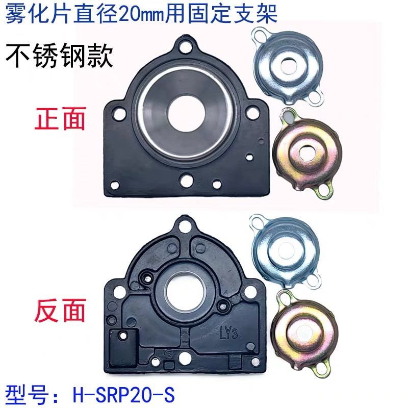
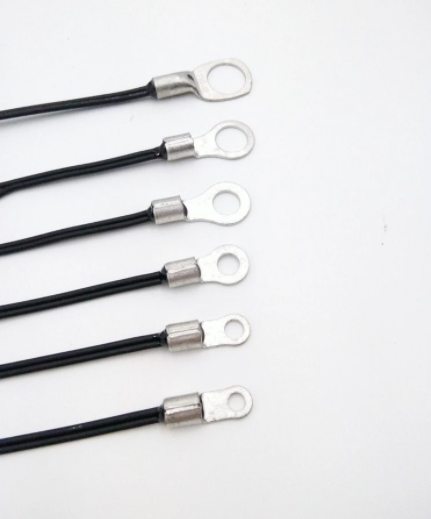
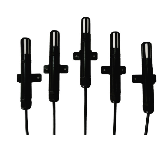
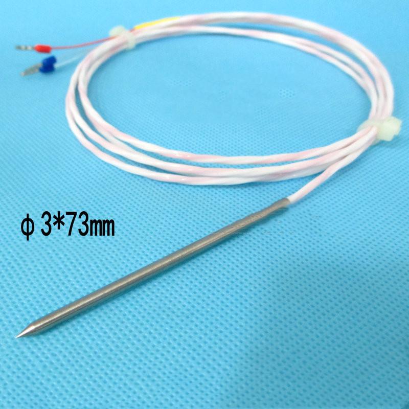
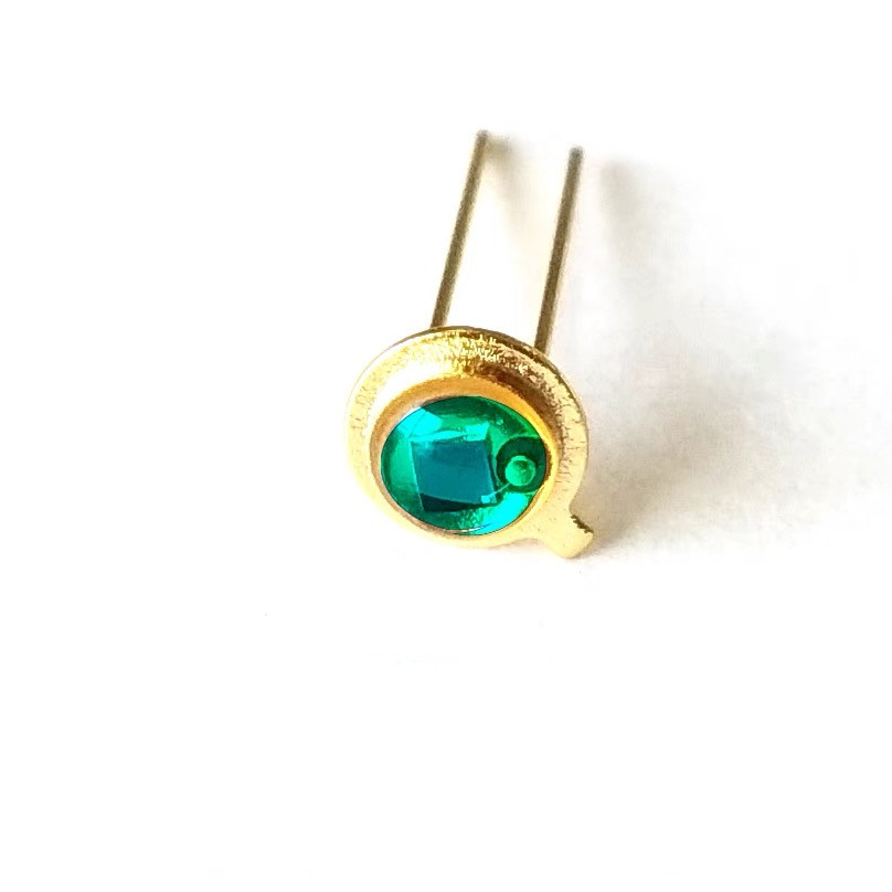
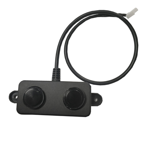
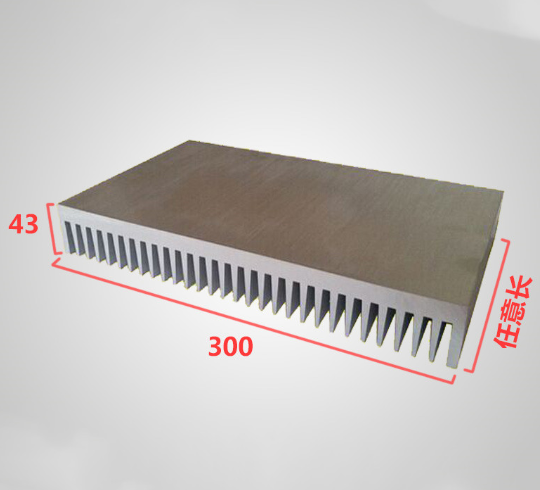
Representative electronic components and custom sub-assemblies fabricated in our onsite-verified Shenzhen facility. Fully compatible with custom OEM FPC antenna feeds and IoT system integration.

Engineering Whitepaper & Technical Analysis

High-Frequency FPC Antenna Design & Substrate Physics

Achieving superior radiation efficiency, controlled characteristic impedance (50Ω ±2Ω), and minimal dielectric loss across Sub-6GHz, UWB, and mmWave bands.

Flexible Printed Circuit (FPC) antennas represent a cornerstone in modern compact wireless product architecture. Unlike rigid PCB trace antennas, which consume expensive planar real estate on main logic boards, or ceramic patch antennas that add vertical height and mass, custom FPC antennas permit engineers to conform radiating structures directly onto curved non-conductive enclosure walls, battery covers, and internal acoustic chambers. However, transitioning from prototype concept to high-volume fabrication demands an in-depth understanding of substrate dielectric dissipation, copper foil grain structure, adhesive loss tangents, and dynamic impedance matching.

1. Substrate Dielectric Selection: Standard Polyimide (PI) vs. Modified Polyimide (MPI) vs. Liquid Crystal Polymer (LCP)

In high-frequency electromagnetic propagation, the dielectric constant (Dk) and dissipation factor (Df, or loss tangent tan δ) of the dielectric core dictate transmission line attenuation and antenna radiation efficiency. For legacy Sub-1GHz protocols (such as LoRa 868/915 MHz or NB-IoT), standard thermoset Polyimide (PI) offers excellent thermal survivability (-200°C to +260°C) and robust dimensional stability. However, standard PI exhibits a significant hygroscopic tendency (moisture absorption rate between 1.5% and 3.0%), which causes the dielectric constant to drift under variable atmospheric humidity, ultimately detuning narrowband resonant peaks.

To mitigate high-frequency insertion loss in dual-band Wi-Fi 6E/7 (2.4 GHz, 5.8 GHz, 6 GHz–7.125 GHz) and 5G New Radio (NR) bands, our Shenzhen factory manufactures custom antennas utilizing Modified Polyimide (MPI) and thermoplastic Liquid Crystal Polymer (LCP). LCP features a quasi-crystalline molecular matrix that reduces moisture absorption to <0.04% while achieving an ultra-low dissipation factor (Df ≤ 0.002 at 10 GHz). This ensures that RF energy is radiated efficiently into free space rather than dissipated as parasitic dielectric heat within the antenna flex core.

Dielectric Material Dk (10 GHz) Df Loss Tangent (10 GHz) Moisture Absorption RF Frequency Suitability Typical Commercial Application
Standard Polyimide (PI) 3.2 – 3.5 0.015 – 0.020 1.8% – 3.0% Sub-3 GHz Bluetooth, BLE, Zigbee, LoRa, 2.4G Wi-Fi
Modified Polyimide (MPI) 2.9 – 3.1 0.004 – 0.006 < 0.5% Up to 15 GHz 5G Sub-6GHz, Wi-Fi 6E/7, UWB Channels 5 & 9
Liquid Crystal Polymer (LCP) 2.8 – 3.0 0.0018 – 0.0025 < 0.04% Up to 110 GHz 5G mmWave (28/39 GHz), Automotive Radar, Satcom
Rigid FR-4 (Baseline) 4.2 – 4.5 0.018 – 0.025 < 0.20% Sub-2.5 GHz Low-cost Mainboard Embedded Antennas

2. Conductor Mechanics: Rolled Annealed (RA) vs. Electro-Deposited (ED) Copper

RF signal propagation at microwave frequencies is constrained to the outermost boundary of the copper conductor due to the electromagnetic skin effect. At 5.8 GHz, the skin depth of copper is approximately 0.85 μm. Consequently, microscopic surface roughness at the copper-dielectric interface induces severe phase distortion and transmission loss.

At Shenzhen Mivo Electronics, our custom OEM FPC antenna fabrication lines specify premium Rolled Annealed (RA) copper foil with surface roughness (Rz) under 1.2 μm, significantly smoother than standard Electro-Deposited (ED) foils. Beyond microwave transmission advantages, RA copper provides superior dynamic fatigue endurance, permitting ultra-tight bend radii (<1.0 mm) without risk of micro-fracturing during assembly into miniature wearable housings or handheld diagnostics instruments.
Custom OEM Topologies

Engineered Antenna Architecture Recommendations

From single-band monopole ribbons to complex multi-input multi-output (MIMO) arrays, we tailor RF radiating geometry to your exact ground plane clearances and casing permittivity.

Dual-Band Wi-Fi 6E/7 & Bluetooth FPC

Dual-resonant Inverted-F (IFA) or Planar Inverted-F (PIFA) architectures covering 2400–2500 MHz and 5150–7125 MHz concurrently.

  • Peak Gain: 3.2 dBi (2.4 GHz) / 4.8 dBi (5.8 GHz)
  • Efficiency: ≥ 70% in free space
  • Feed: 0.81mm / 1.13mm micro-coax with IPEX MHF1/MHF4
  • Adhesive: Genuine 3M 467MP / 9495LE high-tack film

5G NR Full-Band Cellular FPC Antenna

Wideband multi-branch monopole structure covering low-band (698–960 MHz), mid-band (1710–2690 MHz), and Sub-6 GHz (3300–5000 MHz).

  • Voltage Standing Wave Ratio (VSWR): ≤ 2.5:1 across bands
  • Radiation Pattern: Omni-directional azimuth profile
  • Bilateral ground isolation with ferrite suppression layers
  • Available with pre-soldered spring contacts or U.FL leads

Active Multi-Constellation GNSS Flex

High-precision circular polarized reception for GPS L1/L2/L5, GLONASS G1/G2, BeiDou B1/B2/B3, and Galileo E1/E5.

  • Axial Ratio: < 3.0 dB at boresight
  • Integrated low-noise amplifier (LNA) flex option
  • Embedded EMI shielding can with 0.15mm total thickness
  • Ideal for asset trackers and UAV flight controllers

Ultra-Wideband (UWB) Decawave/NXP Tuned

Engineered specifically for micro-location centimeter accuracy ranging across Channel 5 (6.48 GHz) and Channel 9 (7.98 GHz).

  • Flat group delay variation: < 150 ps
  • Return Loss (S11): < -15 dB across 6.2–8.2 GHz
  • Modified Polyimide substrate prevents pulse ringing
  • Engineered for digital car keys and RTLS personnel tags

Sub-1GHz ISM & LoRaWAN Flex Antenna

Miniature meander-line inductive topology tuned for 433 MHz, 868 MHz (EU), and 915 MHz (US) telemetry.

  • Compact footprint: Over 60% smaller than 1/4 λ whip
  • Input Impedance: Directly matched to 50Ω single-ended
  • High thermal tolerance for outdoor environmental sensing
  • Integrates seamlessly with Mivo distance & temp probes

NFC & Wireless Power Transfer (WPT) Coils

High-Q inductive planar spiral coils fabricated on ultra-thin flexible copper-clad laminate with high-permeability ferrite sheets.

  • Resonant frequency: 13.56 MHz (ISO/IEC 14443 Type A/B)
  • Sintered ferrite sheet thickness: 0.05mm to 0.20mm
  • Suppresses eddy-current cancellation on metal battery surfaces
  • Integrated payment, point-of-sale, and IoT provisioning
Market Intelligence & Strategic Sourcing

FPC Antenna Procurement Trends (2025–2030)

Anticipate supply chain dynamics, environmental regulatory shifts, and emerging RF integration paradigms to protect your product roadmap and cost structure.

1. LCP Mainstream Adoption

As wireless products embrace Wi-Fi 7 and early 6G sub-THz bands, procurement teams are rapidly migrating from legacy PI to LCP. Despite a 15–25% raw material cost delta, LCP delivers superior yields in fine-pitch sub-millimeter RF feed traces, yielding net lower system lifecycle costs.

2. Co-Packaged Flex Sensors

Hardware designers increasingly bundle FPC antennas with embedded NTC thermistors, capacitive touch pads, or optical photodiode interconnects on a singular multi-tier flex substrate. This eliminates connector overhead and streamlines final enclosure assembly.

3. In-Mold Electronics (IME)

The convergence of FPC antenna manufacturing with thermoforming structural plastics enables conductive antenna patterns to be directly embedded within cosmetic device housings, saving interior enclosure volume and enhancing IP68 environmental sealing.

4. Supply Chain De-risking

Global OEMs are consolidating vendors by contracting onsite-verified factories capable of turnkey raw flex fabrication, laser drilling, surface mount assembly (SMT), vector network testing, and cable harness termination under one accountable quality management umbrella.

Why Global B2B Buyers Trust Us

Onsite-Verified Shenzhen Manufacturing Capabilities

Combining world-class PCB/FPC fabrication, automated SMT lines, custom sensor production, and rigorous 100% vector network analyzer RF testing.

Shenzhen Mivo Electronics Co., Ltd. operates an onsite-verified production facility situated in the heart of the global electronics capital—Shenzhen, Guangdong. With over 8 years of premier international exporting experience, we maintain an established reputation as an accountable manufacturing partner for engineers, system integrators, and Fortune 500 sub-assembly buyers across North America, Europe, and Asia-Pacific.

Our turnkey manufacturing framework spans raw substrate preparation, laser direct imaging (LDI), vacuum laminating, surface finishing (ENIG, Immersion Silver, OSP), automated SMT placement of fine-pitch components down to 01005 passives, and precision micro-coaxial cable soldering. Whether you require a fast-turn 5-piece prototype for anechoic chamber tuning or 500,000-piece monthly mass production, our ISO-aligned workflows guarantee batch-to-batch impedance uniformity and strict VSWR conformance.

Factory Verification Matrix

Corporate Entity Shenzhen Mivo Electronics Co., Ltd.
Operational Facility Yuanshan St, Longgang, Shenzhen, China
Onsite Verification Verified by Third-Party Inspection
Export Experience 8+ Consecutive Years
Buyer Satisfaction Rating 4.7 / 5.0 Verified Score
Workforce & Staff 51 – 100 Engineering & QC Specialists
Prototype MOQ Flexible from 5 Pieces
Core Product Scope FPC Antennas, PCBA, RTD/NTC Sensors
2016
Established
8+ Yrs
Global Exporter
4.7/5
Buyer Rating
5Pcs
Prototype MOQ
50Ω±2
RF Impedance
100%
VNA Tested
Procurement & Engineering Due Diligence

Frequently Asked Questions for Sourcing Managers

Critical technical, testing, file preparation, and logistics considerations answered by our senior RF application engineering staff.

How do you manage antenna frequency detuning caused by customer plastic enclosures?
Plastic injection materials (ABS, PC, Nylon) possess relative dielectric constants typically ranging from 2.5 to 3.8. When an FPC antenna is adhered to the inside of an enclosure, this dielectric loading shifts the resonant frequency downward (frequency detuning). During our DFM and prototype development phase, we request 3D STEP models and sample enclosures from the buyer. Our engineers perform 3D electromagnetic simulations (HFSS/CST) and chamber vector network analyzer (VNA) sweeps inside the actual enclosure, pre-shifting the conductive trace geometry upwards so that the antenna resonates exactly at the target operational frequency once installed in your final housing.
What design files and specifications are required to receive a formal DFM review and quotation?
To provide an exhaustive engineering quote within 24 hours, please supply: (1) Gerber files (RS-274X format) or ODB++ detailing conductor traces, solder mask/coverlay, stiffeners, and profile cutouts; (2) Mechanical drawing indicating overall dimensions, bend zones, 3M adhesive boundary, cable solder pad locations, and micro-coaxial connector orientation; (3) RF specification parameters including target bands, minimum gain (dBi), peak VSWR, and allowable return loss; (4) Total initial prototype quantities and forecasted mass-production volume.
Which micro-coaxial cables and connector terminations can be integrated during assembly?
We operate precision automated stripping and hot-bar soldering stations designed for micro-coaxial transmission lines. Available cable diameters include 0.81mm, 1.13mm, 1.32mm, 1.37mm, and 1.78mm (RG-178), available in custom lengths from 20mm to 1000mm. For terminations, we support Hirose U.FL, IPEX MHF1, MHF4, SMA bulkhead, MMCX, or stripped/tinned ends for direct PCB through-hole and surface-mount soldering. Every terminated cable harness undergoes strict pull-force retention testing and automated coaxial impedance inspection.
Can Mivo supply complete turnkey assemblies combining FPC antennas with sensors and stiffeners?
Yes. A primary differentiator of Shenzhen Mivo Electronics is our one-stop integration capacity. We frequently assemble rigid-flex hybrid assemblies where an FPC antenna is integrated with PT100 RTD sensor leads, NTC battery temperature sensors, humidity transducers, or SMT matching circuits (inductors, capacitors, TVS diodes). Additionally, we can bond localized FR-4, polyimide, stainless steel, or aluminum stiffeners behind connector landing pads to ensure mechanical durability during mating cycles in end-customer factories.
How do you ensure batch-to-batch consistency and electrical impedance tolerance in mass production?
Consistent 50Ω characteristic impedance is maintained through tight closed-loop process controls: (1) High-accuracy Laser Direct Imaging (LDI) maintaining trace width/space tolerances within ±12 μm; (2) Controlled-depth vacuum hot press lamination ensuring constant coverlay adhesive thickness; (3) 100% coupon impedance testing via Time Domain Reflectometry (TDR) on every production panel; (4) Lot-based Over-The-Air (OTA) chamber testing validating Total Radiated Power (TRP) and Total Isotropic Sensitivity (TIS).

Ready to Optimize Your Wireless Device Performance?

Connect directly with our Shenzhen senior RF engineering team for a complimentary DFM analysis, stack-up optimization, and quotation for custom OEM FPC antennas, sensor modules, or turnkey PCBA assemblies.